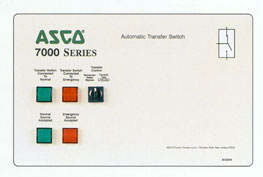
ASCO Control Panel Standard Features - Series 7000 & 7000 Service Entrance**
- Switch position indicating lights (16 mm, industrial grade LED's).
- Source acceptability indicating lights with true indication of the acceptability of each source, as determined by the voltage, frequency, voltage unbalance, and phase sequence settings of the control panel (16mm, industrial grade LED's).
- Three position (16mm, industrial grade type) selector switch:
- Automatic: Normal maintained position.
- Test: Momentary position to simulate normal source failure for system test function.
- Reset Delay Bypass: Momentary position to bypass transfer and re-transfer time delay.
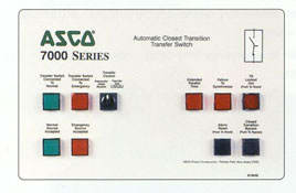
- Extended Parallel Time - Provides visual indication when the pre-set extended parallel time is exceeded and automatically opens the emergency or normal main contacts. The ATS remains locked out until the alarm reset switch is operated.
- Failure To Synchronize - Visually displays a failure to synchronize alarm if the time delay settings is exceeded.
- TS Locked Out - Prevents transfer in either direction if the extended parallel time is exceeded.
- Alarm Reset - Resets extended parallel and failure to synchronize alarms.
- Closed Transition Bypass - Allows transfer between sources in an open transition mode.
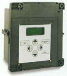
The 7000 Series microprocessor controller is a Transfer Control Center which allows the user to easily access detailed information on: system status; power source parameters; voltage, frequency and time delay settings; optional feature settings; historical event log; and system diagnostics. A four line, (20) character LCD has a backlit display which enables easy viewing under all conditions. The user can navigate through all screens using only six buttons, which also allows selection of: (18) different source parameter settings; (16) standard time delays; (12) standard feature settings; up to (7) independent engine exercise routines; and even the language (English, German, Spanish, French, etc.) which appears on the display.
Since the Transfer Control Center must be visible and operable through the enclosure door, it has been qualified for use in industrial and outdoor applications. This includes installation in Type 3R (outdoor/rainproof), 4 (weatherproof) and 12 (indoor/industrial) enclosures.
|
|
||
| 7000 Series Transfer Control Center Screens | ||
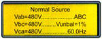
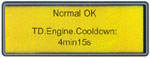
| Status | System Status | Source Status |
 |
 |
|
| Displays system status in clear, concise language. Message shown indicates normal source is acceptable and the load is connected to the normal source. | Displays voltage for each phase, frequency, phase rotation and voltage unbalance for both normal and emergency sources. | |
|
|
||
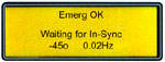
| Settings | Time Delay Status | In-Phase Transfer Mode |
 |
 |
|
| Active time delay status displays time remaining until next control event. | Displays the relative phase angle between sources and frequency differential to indicate the controller is awaiting and in-phase condition. | |
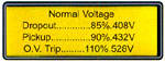
| Voltage and Frequency Settings | Time Delay Settings | |
 |
 |
|
| Provides voltage and frequency setting values for normal and emergency sources. Voltage pick-up, dropout and trip settings are set in percentage of nominal voltage and are also displayed in RMS voltage values. | Provides direct reading for setting time delays. | |
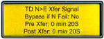
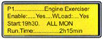
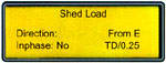
| Engine Exerciser | Feature Settings | |
 |
 |
|
| Seven independent programs, load/no load selection, flexible run times and daily, weekly, bi-weekly and monthly exercise routines. | Standard features can be activated with the keypad. As an example, when enabled, the "shed load" option causes the transfer switch to transfer the load off of the specified source. If desired, the load shed transfer can be made in-phase. | |
|
|
||
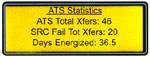
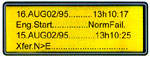
| Data Logging | ATS Statistics | Historical Event Log |
 |
 |
|
| Instant availability of statistical information on total number of ATS transfers, number of transfers caused by power failures and total days controller has been energized, plus more. | Displays detailed information for last 99 events, including time of occurrence, length of event, date and reason for event. | |